Top 5 Best Practices When Building a USB 3.1 Vision System
Getting the most out of FLIR's USB 3.1 cameras
Article Breakdown:
-
- USING USB 3.1 ON A LAPTOP
- EXTENDING THE WORKING DISTANCE OF USB 3.1
- MAXIMIZING USB 3.1 BANDWIDTH
- IMPLEMENTING A MULTIPLE USB 3.1 CAMERA SYSTEME
- USING USB 3.1 WITH THIRD PARTY APPLICATIONS
Top 5 Best Practices When a Building USB 3.0 Vision System.pdf
If you have already done your research and selected USB 3.1 as the interface for your next vision application, this article will help you through the next phase of your development by offering some best practices to follow for a smooth and easy system integration. For example, what is the best laptop configuration for USB 3.1? What is the maximum cable length USB 3.1 can support? And how can USB 3.1 be used for a system with multiple cameras? FLIR has polled our Customer Support team and after more than two years of supporting USB 3.1 customers, these are the most common challenges they see customers face and how they have resolved them.
![]()
Best practice for using USB 3.1 on a laptop
Many users choose USB 3.1 because it is easy to use and plug and play. Fewer and fewer laptop computers, for example, are coming with an ExpressCard slot, which was historically used to support add-in cards for other digital interfaces. Having both data and power through the same cable allows USB 3.1 cameras to be deployed easily without additional hardware. In a mobile application, you can connect the camera directly to a USB 3.1 enabled laptop and start using the camera right away. However this may not be true for some laptops due to issues with power or cable length.
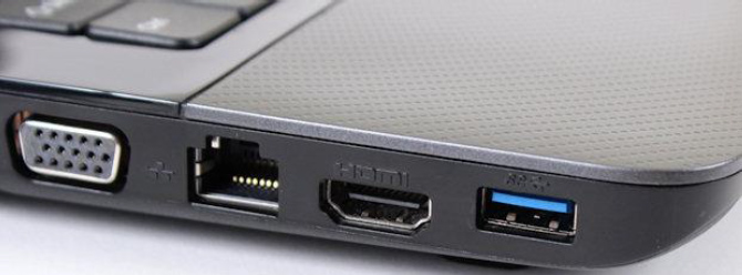
Figure 1. The signature pantone blue USB 3.1 port on a laptop
A single USB 3.1 port is designed to provide up to 4.5 W of power, and while USB 3.1 is backward-compatible with USB 2.0, the power delivery with each standard is quite different. Most USB 2.0 provides 500mA at 5V, or 2.5 W of power. However, for both USB 3.1 and USB 2.0 there may be small variations in the amount of available power, due to differences in motherboard design and the USB host controller chip being used. This becomes a factor to consider depending on the amount of power required by the camera. For example, FLIR’s Flea3 USB 3.1, an ice-cube size CMOS camera, has an average power consumption of about 2.5 W. On the other hand, FLIR’s high performance Grasshopper3 USB 3.1, utilizing a dual tap 6 Megapixel CCD, has an average power consumption of 4 W. To prevent or address problems related to the USB port not delivering enough power, choose USB 3.1 cameras that can optionally be powered externally via a GPIO connector (see Figure 2).
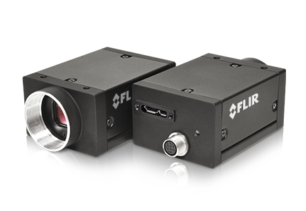
Figure 2. FLIR Grasshopper3 camera with Micro-B USB 3.1 connector, and GPIO connector
There are also factors to consider when selecting a USB 3.1 cable to use with a laptop. Most USB 3.1 camera vendors offer cables up to 5 meters long. These longer cables, however, are often tested on a PC, where PCI-Express host controller cards are used. On a PCIe card, the physical USB 3.1 host controller chip and the USB 3.1 ports are close together, so the printed circuit board (PCB) “traces” are very short (see Figure 3). On laptop computers, however, where the motherboard circuit design is compact, the PCB traces may be very long. In these cases the length of the physical USB 3.1 cable plus the length of the PCB trace may make the effective cable distance too long, and make the connection unstable. In these cases it is best to use a slightly shorter cable, or purchase a higher quality cable suited for industrial applications. Please refer to the next section for more information on extending cable lengths for USB 3.1.
Best practice for extending the working distance of USB 3.1
Cameras and the host system may not always be next to each other. Many applications require long cable lengths to connect the camera to the host PC. A wide variety of solutions exist on the market today, including passive cables, active cables and fiber extenders. Understanding the differences between these solutions will ensure the most reliable and cost-effective solution is used.
Passive cables are the most common and cost effective solution and typically come in lengths up to 5 meters. The challenge with extending cable lengths using a passive copper cable is signal loss. As the cable length increases, signal loss starts to become significant enough to impact performance. Factors affecting the signal loss include cable design, cable material choice, and the connector termination. Vendors will evaluate cable characteristics such as common mode conversion and intra pair skews to determine the best construction and material to use with a USB 3.1 camera. It is recommended to purchase well tested cables from your camera vendor or an industrial cable vendor.
As cable distances increase, cable vendors start to embed silicon chips in the cable in order to maintain signal quality, creating an active cable. This allows copper cables to run up to 20 meters while still being cost effective. However as the distance continues to increase, more silicon chips need to be embedded in the cable which complicates the design and increases the difficulty of manufacturing. At 20 meters or above, you should start to look for fiber-based solutions instead of copper solutions.
A fiber extender consists of two transceivers that convert the electrical signal to an optical signal and vice versa. The two transceiver units are connected via a fiber cable that can carry the optical signal but cannot transmit power. Since power cannot be transmitted using the fiber cable, an external power source will be required to power the transceiver module and the camera. Most vendors integrate the transceiver module with a proprietary hub. By powering the hub, the transceiver and camera will be powered at the same time.
While it’s possible to use any of these cable solutions to extend cable distance, understanding differences between the solutions allows you to choose the one that best fits your application while minimizing system footprint, complexity, and cost.
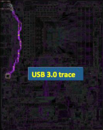
Figure 3. PCB trace between a USB 3.1 port and the physical host controller on a motherboard, highlighted in purple
Best practice for maximizing USB 3.1 bandwidth
USB 3.1 supports Direct Memory Access (DMA) which minimizes CPU usage. This is a critical feature for high bandwidth applications. USB 3.1 cameras integrate high throughput imaging sensors such as Sony IMX174 and CMOSIS CMV4000, outputting over 370 MB/s of data and pushing the limits of USB 3.1, which supports approximately 440 MB/s. You must have a high performance PC in order to receive and process all this data. PC component selection becomes an important aspect of system design in order to avoid performance bottlenecks.
While there are many USB 3.1 host controller cards on the market, cards with newer USB 3.1 host controller chipsets such as the Fresco FL1100, the Renesas μPD720202, or Intel are able to sustain higher bandwidth than previous generation chipsets. If you are integrating an existing PC system you also need to be mindful of the PCI Express version of the motherboard. Systems using a single lane (x1) PCI Express 1.0 interface will not support the full transfer speed of USB 3.1. This is more often encountered by laptop users since the PCI Express version is not usually a published specification of the laptop. To run USB 3.1 cameras at full frame rate use a PCIe 1.0 x4 interface (1GB/s) or a newer version of PCIe, such as PCIe 2.0 (500 MB/s per lane) or 3.0 (985 MB/s per lane).(See picture of PCIe cards) If there is an opportunity to purchase a new PC, new chipsets offering integrated Intel host controllers such as Z77 (Ivy Bridge) or Z87 (Haswell) often have the best performance. These chipsets can also be found in tablets and laptops currently on the market such as the Microsoft Surface Pro 2.
The component selection does not end at the USB 3.1 port. With 370 MB/s of data coming in, you will need to ensure the rest of the PC specification is capable of processing large amounts of data. You may want to choose a discrete video card in order to offload image display from the CPU to the video card. If you want to write large amounts of image data to the disk you may want to consider Solid State Drives (SSD) or RAID arrays.
When deploying a USB 3.1 camera in a high bandwidth application, you should evaluate each stage of the imaging pipeline to ensure you select the proper hardware and eliminate performance bottlenecks.
Best practice for implementing a multiple USB 3.1 camera system
Motherboards that support USB 3.1 typically offer 2-8 USB 3.1 ports. You can further expand the number of ports by using USB 3.1 hubs or USB 3.1 host controller cards.

Figure 4. A motherboard with 8 USB 3.1 ports
USB 3.1 hubs come in all shape and sizes, utilizing USB 3.1 hub controllers from different chipset vendors. The hubs can be plugged into existing USB 3.1 ports on a PC which means all data is funneled through the same port on the host PC and bandwidth is shared by all the ports on the hub. The bandwidth of each camera will need to be managed separately to avoid data loss from overflowing the bus. Most USB 3.1 cameras support bandwidth throttling which allows you to set the maximum bandwidth the camera will consume. You will also find hubs with newer USB 3.1 hub host controllers to have better performance in terms of overall throughput when compared to earlier generation controllers. These controllers include VIA VL812, Genesys Logic GL3520 and Renesas uPD720210. Hubs also offer additional benefits such as increasing the working distance of the system.
A multi-port host controller card is another method for adding more USB 3.1 ports to your system. These cards connect directly to a PCI-Express on the motherboard. Most cards on the market are single controller cards where the overall bandwidth is shared by all the ports on the card. Cards with multiple controllers are also available from some vendors, matching each port with a host controller, hence enabling full bandwidth per port. However these cards usually require a larger PCI-Express slot, such as a slot with x4 lanes or x8 lanes.
Best practice for using USB 3.1 with third party applications
Most camera vendors provide an Application Programming Interface (API) to develop with the camera. The API typically offers camera control but no image processing libraries. You may want to develop your own image processing algorithm such as optical character recognition (OCR) or use the camera with an existing image processing library from a third party vendor. With so many software packages and camera vendors, the need for interoperability has motivated standardization and a common way for cameras and software applications to communicate with each other.
![]()
Figure 5. GenICam and USB3 Vision logo
The USB3 Vision committee was formed in 2011 with the purpose of creating and managing a camera control and streaming standard for USB 3.1 cameras. The committee wanted to build on the existing standardization effort, made possible by GigE Vision. GigE Vision is a standard designed for Ethernet cameras and developed based on GenICam that has gained popularity over the last several years. The GigE Vision standard defines a stream and control protocol, which leverages the success of GenICam by relying on a standard format naming convention (SFNC) to maintain consistency in functionality and attribute naming.
USB3 Vision, which was finalized and released on January 18, 2013, also uses GenICam. This benefits both camera users and software vendors. On the camera side, you only need to familiarize yourself with one set of camera attributes and controls. On the software side, the software only needs to support a single set of standard attributes and controls, allowing you to use any USB3 Vision compliant camera with the software. Camera vendors such as FLIR have been shipping their cameras with USB3 Vision support since August 2013, with software vendors such as National Instruments and A&B Software releasing their software with support for USB3 Vision cameras as well.
For vendors who don’t have support for USB3 Vision, a proprietary interface or plugin can still be used with a third party application. For example, several camera vendors provide a Cognex VisionPro AIK package, which acts as a translational layer between the vendor API and Cognex API.
Summary
FLIR is not only committed to bringing the newest sensor technology to USB 3.1, we also want to share our best practice principles to help you integrate USB 3.1 cameras in to your system. Laptop users should select a camera that can be powered externally and use recommended cables from their vendors. Choosing the correct solution to extending USB 3.1 cable distance will reduce system complexity and cost. For setting up a multiple camera system or maximizing bandwidth, you should consider the entire imaging pipeline to select the right components to use and eliminate bottlenecks. Using a camera with USB3 Vision support will ensure the system maintains interoperability and avoid vendor lock-in. For more detailed information, please visit www.ptgrey.com for knowledge base articles, application notes and white papers on the latest USB 3.1 camera and technology.