Mean Time Between Failures (MTBF)
MTBF (Mean Time Between Failures) is a measurement provided by request. For reliability information, please contact Technical Support.
MTBF compares the failure rate over time for a population of units by measuring the elapsed time in hours between inherent failures of a product or system during operation. It is usually applied to products that are repairable after failure, or where failure does not require repair or interfere with overall operating system.
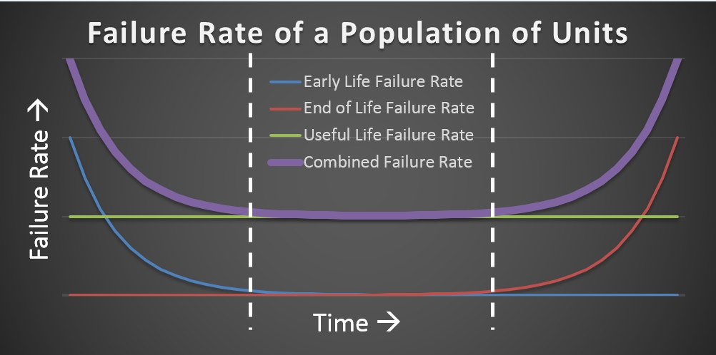
MTBF results often follow a “bathtub curve.” This curve illustrates typical failure rates during the three periods of a unit’s life:
-
- Early Life
Marked by a decreasing failure rate as stress testing identifies and removes weaker units. It also includes failures caused by handling and installation errors. It is sometimes called the “burn-in” period. - Useful Life
Marked by a comparatively level and predictable failure rate, where failures are random. This is often the time when a product reaches consumers and it represents the “normal” or “steady” state. - End of Life
Marked by a noticeable increase in failure rates as the units age and the result of material fatigue and other types of stress become evident. This is also called the “wear-out period.”
- Early Life
Note: The MTBF shows the expected value (mean) of the probability distribution and predicts the reliability of a unit. It is not a guarantee of the service life of a unit.
Here is an explanation of our method of calculating MTBF, which focuses on the useful-life period.
-
- Calculation Model: Telcordia SR-332 Issue 3
- Calculation Method: Method II: Unit steady-state failure rate using manufacturer's test data for each component
- Environment:
- Air—Ground, fixed, uncontrolled (moderate environment stress, airflow available)
- No Air—Ground, fixed, uncontrolled (higher environment stress, no airflow available)
- Operating Temperature: based on the operating temperature range of the model's specifications. Note: This range reflects the ambient temperature only; the internal temperature of the camera is not considered.
- Quality Level: Level II
- commercial grade components
- procured with thorough device qualification and specifications
- device and manufacturers qualified and identified on approved lists
- lot control to ensure consistent quality
- Burn-in Time: 5 hours @ 50°C
- The analysis is for unit-level device hardware failures. Transient, manufacturing process, software, and procedural error failures are not included.
- The analysis focuses on the useful life period. The end of life period is not considered.
- Field and manufacturer test data is utilized when available. Data is normalized to operating temperatures using the Arrhenius temperature model.
- Stress and thermal rise parameters are calculated for components considered high power. The default 50% stress is used for all other components.
- Component thermal rise is applied only when greater or equal to 5°C.