Geometric Vision using Ladybug Cameras
Effective warping and stitching of the images produced by the camera system's six sensors is achieved through accurate calibration of the physical location and orientation of the sensors and the distortion model of the lens. This calibration also enables photogrammetric analysis of image data. This application note describes how to map between the camera coordinate system and individual sensors.
Coordinate Systems on Ladybug Cameras
Each lens has its own right-handed 3D coordinate system. As well there is a Ladybug 3D Coordinate system that is associated with the camera as a whole. This makes a total of seven 3D coordinate systems on every Ladybug camera. As well, there is a 2D pixel-grid coordinate system for each sensor.
Lens 3D Coordinate System
Each of the six lenses has its own 3D coordinate system.
- Origin is the optical center of the lens
- Z-axis points out of the sensor towards the scene – i.e. it is the optical axis
- The X- and Y-axes are relative to the pixel grid of the image sensor associated with that lens
- The Y-axis points along the image columns. The positive Y direction is in the direction of ascending row number. This points down from the point of view of a normally oriented image
- The X-axis points along the image rows. The positive X direction is in the direction of ascending column number. This points to the right in a normally oriented image
- This coordinate system is used to represent 3D space from the point-of-view of each lens/sensor pair. Its units are meters, not pixels.
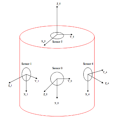
Figure 1: 3D Sensor Coordinates
Sensor 2D Coordinate System
Each sensor has its own 2D coordinate system.
- The u- and v-axes are the image based 2D image coordinate system for the rectified image space and are measured in pixels
- The origin of the coordinate system is at the intersection of the optical axis and the rectified image plane and differs for each sensor
- The u-axis points along the rows of the image sensor in the direction of ascending column number (i.e. to the right)
- The v-axis points along the columns in the direction of ascending row number (i.e. down).

Figure 2: 2D Sensor Coordinates
Ladybug Camera Coordinate System
The Ladybug Camera coordinate system is centered within the Ladybug case and is determined by the position of the 6 lens coordinate systems.
- Origin is the center of the five horizontal camera origins
- Z-axis is parallel to the optical axis of the top lens (lens 5) (*)
- X-axis is parallel to the optical axis of lens 0 (*)
- Y-axis is consistent with a righthanded coordinate system based on the X- and Z-axes
- There may be some variations from LD2 – LD3 – LD5
- (*) Note –due to assembly tolerances the optical axes of lens 5 and lens 0 will typically not be perfectly perpendicular. The X-axis of the Ladybug Camera coordinate system is adjusted slightly to ensure that they are perpendicular.
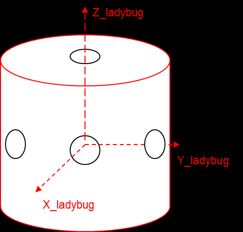
Figure 3: Global Coordinates
Relating Lens Coordinate Systems and the Ladybug Coordinate System
The position of each lens coordinate system relative to the Ladybug coordinate system is retrievable from the Ladybug API. First, use ladybugGetCameraUnitExtrinsics() defined in ladybuggeom.h to retrieve the 3D translation and Euler angle defined rotation.
/**
* Gets the 6-D extrinsics vector for the specified camera unit.
*
* The 6-D extrinsics vector is in EulerZYX convention (see Craig's
* Introduction to Robotics pg. 45-49). The ordering of the extrinsics
* components are :
*
* - element 0 - Rx - Rotation about X (radians)
* - element 1 - Ry - Rotation about Y (radians)
* - element 2 - Rz - Rotation about Z (radians)
* - element 3 - Tx - Translation along X (meters)
* - element 4 - Ty - Translation along Y (meters)
* - element 5 - Tz - Translation along Z (meters)
*
* By extrinsics, we mean that the corresponding 4x4 transformation matrix
* allows one to map a point in the local camera unit coordinates to that
* of the Ladybug coordinate frame. Where s=sin and c=cos, the format of the
* matrix is given below.
*
* Example:
* To map this to Craig's matrix:
* - Rz = alpha
* - Ry = beta
* - Rx = gamma
*
* - |X'| |((cRz)(cRy)) ((cRz)(sRy)(sRx)-(sRz)(cRx)) ((cRz)(sRy)(cRx)+(sRz)(sRx)) Tx||X|
* - |Y'|=|((sRz)(cRy)) ((sRz)(sRy)(sRx)+(cRz)(cRx)) ((sRz)(sRy)(cRx)-(cRz)(sRx)) Ty||Y|
* - |Z'| |((-sRy)) ((cRy)(sRx)) ((cRy)(cRx))) Tz||Z|
* - |1 | |0 0 0 1 ||1|
*
* @param context - The LadybugContext to access.
* @param uiCamera - Camera index of interest.
* @param ardEulerZYX - The returned 6-D EulerZYX extrinsics vector.
*
* @return A LadybugError indicating the success of the function.
*/
LADYBUGDLL_API LadybugError
ladybugGetCameraUnitExtrinsics(
LadybugContext context,
unsigned int uiCamera,
double ardEulerZYX[6] );
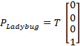
Note the function comments illustrate how to convert the provided Euler angles (Rx, Ry, Rz) and translation (Tx, Ty, Tz) into a 4x4 Transform T. Using standard homogeneous transform formulation:
![]()
Where  in the appropriate coordinate frame.
Once this homogeneous transform is obtained, it can be used to calculate the lens coordinate frame origin in the Ladybug coordinate frame, or the lens coordinate frame axes in the Ladybug coordinate frame, and vice versa.
Converting a Pixel Location to a 3D Ray
A common task when using the Ladybug camera for geometric vision is to interpret a pixel location in a particular image to a 3D ray in the Ladybug Coordinate System. There are a variety of image spaces from which the pixel may be extracted – for example, spherical, cylindrical, rectified or raw. Users are encouraged to use raw images for this kind of application. Raw images are the only images which have not been resampled and consequently should provide the best accuracy when finding or tracking image features.
To convert a pixel location in a raw image to a 3D ray in the Ladybug Coordinate System the following steps should be taken:
1. Obtain the focal length for the appropriate camera using ladybugGetCameraUnitFocalLength()
2. Obtain the image center for camera using ladybugGetCameraUnitImageCenter()
3. Obtain 6D extrinsics vector (Euler angles and translation) for the camera using ladybugGetCameraUnitExtrinsics()
4. Rectify 2D pixel location using ladybugRectifyPixel()
5. Find the (u,v) pixel coordinate for this rectified image location
6. Transform the rectified 2D pixel location into a 3D ray within the local camera coordinate system
7. Transform the local 3D ray to a 3D ray in the Labybug Coordinate System
To find the (u,v) pixel location from a rectified (column,row) image position, the image center information must be taken into account:
![]()
![]()
Where ![]() equals the pixel row position and equals the image center row position.
equals the pixel row position and equals the image center row position.
The rectified image position (u,v) can be transformed to a local 3D ray value by interpreting the rectified image using the standard pin-hole camera model. Note that the focal length and image center obtained for the camera is in pixels and is valid only for the rectified image of the specified camera. To calculate the local 3D ray from the rectified 2D pixel location Z is arbitrary and can be set to 1. Applying the pin-hole model equations then yields:
![]()
![]()
![]()
The vector . To convert this vector to the Ladybug Coordinate System, one simply applies the 3x3 rotational component of the homogeneous transform shown in section 1.5:
![]()
Where R is the upper-left 3x3 submatrix of T. The origin of this vector will be the origin of the local coordinate system transformed into the Ladybug Camera coordinate system, or
Converting a Pixel Location to a 3D Ray Corrected for Lens Offset
Mapping a 2D raw pixel to a 3D ray is complicated by the fact that each lens center is offset from the center of the Ladybug Coordinate System. To get the most accurate results the ray has to have both a starting point and a direction – not just a direction from the center of the Ladybug Coordinate System.
Mapping a raw pixel proceeds in two steps:
1. Map the raw pixel to its rectified coordinates – API: ladybugRectifyPixel()
/**
* Maps a distorted (raw) pixel location to its corresponding point in the
* rectified image.
*
* This function must be called after ladybugSetOffScreenImageSize(), which
* sets the resolution of rectified images.
*
* @param context - The LadybugContext to access.
* @param uiCamera - Camera index that this image corresponds to.
* @param dDistortedRow - Row coordinate of the distorted (raw) pixel to map.
* @param dDistortedCol - Column coordinate of the distorted (raw) pixel to map.
* @param pdRectifiedRow - Location to return the row coordinate of the same point
* in the rectified image.
* @param pdRectifiedCol - Location to return the column coordinate of the same
* point in the rectified image.
*
* @return A LadybugError indicating the success of the function.
* LADYBUG_OVEREXPOSED is returned if the selected region's average
* intensity exceeds 254/255 for any channel.
*
* @see ladybugSetOffScreenImageSize()
*/
LADYBUGDLL_API LadybugError
ladybugRectifyPixel(
LadybugContext context,
unsigned int uiCamera,
double dDistortedRow,
double dDistortedCol,
double* pdRectifiedRow,
double* pdRectifiedCol
2. Map the rectified coordinates to a ray location and direction – API: ladybugRCtoXYZ()
/**
* Projects a 2D point on a specific camera unit into a 3D ray in the Ladybug
* coordinate frame. The ray is defined as its starting point and direction.
* The starting point takes into account the camera unit's offset from the
* center of the ladybug camera which allows accurate projection of the
* ray at distances different from the stitching radius.
*
* @param context - The LadybugContext to access.
* @param dRectifiedRow - The rectified row of the 2D input point.
* @param dRectifiedCol - The rectified column of the 2D input point.
* @param uiCamera - The camera unit.
* @param pdLocationX - The output ray location x component.
* @param pdLocationY - The output ray location y component.
* @param pdLocationZ - The output ray location z component.
* @param pdDirectionX - The output ray direction x component.
* @param pdDirectionY - The output ray direction y component.
* @param pdDirectionZ - The output ray direction z component.
*
* @return A LadybugError indicating the success of the function.
*/
LADYBUGDLL_API LadybugError
ladybugRCtoXYZ(
LadybugContext context,
double dRectifiedRow,
double dRectifiedCol,
unsigned int uiCamera,
double* pdLocationX,
double* pdLocationY,
double* pdLocationZ,
double* pdDirectionX,
double* pdDirectionY,
double* pdDirectionZ);
Example code for this mapping type, and other mapping types that don’t rely on the API functionality as heavily, is available in the ladybugTranslate2dTo3d example, included with the Ladybug SDK.
Converting a 3D Point to a Pixel Location
Reversing the pixel-to-3D problem described in section 1.6 and 1.7 is slightly complicated by the requirement to first find which lens a 3D point will project into. Otherwise it is straightforward using the function ladybugXYZtoRC(). The function header information is provided below.
/**
* Projects a 3D point (with respect to the Ladybug coordinate frames) onto
* the indicated camera unit and returns where it will falls on its rectified
* image.
*
* @param context - The LadybugContext to access.
* @param dLadybugX - X coordinate of the point to project.
* @param dLadybugY - Y coordinate of the point to project.
* @param dLadybugZ - Z coordinate of the point to project.
* @param uiCamera - Camera index this image corresponds to.
* @param pdRectifiedRow - The returned rectified row location where the 3D point
* falls (Will be less than 0 if the point does not
* project to the rectified image).
* @param pdRectifiedCol - The returned rectified column location where the 3D point
* falls (Will be less than 0 if the point does not
* project to the rectified image).
* @param pdNormalized - The distance from the rectified pixel to the focal center
* normalized by the focal length. Can be set to NULL if
* the caller is not interested in this value.
*
* @return A LadybugError indicating the success of the function.
*/
LADYBUGDLL_API LadybugError
ladybugXYZtoRC(
LadybugContext context,
double dLadybugX,
double dLadybugY,
double dLadybugZ,
unsigned int uiCamera,
double* pdRectifiedRow,
double* pdRectifiedCol,
double* pdNormalized);
To determine which lenses a 3D point will project into, this function can be used for each of the 6 lens locations (by setting the uiCamera parameter appropriately). If the return code is successful (LADYBUG_OK) then the 3D point defined by dLadybugX, Y and Z projects into camera uiCamera at the rectified row,column position provided by pdRectifiedRow and pdRectifiedCol. The location of the pixel in the raw image can be determined by using ladybugUnrectifypPixel.
Calibration Accuracy
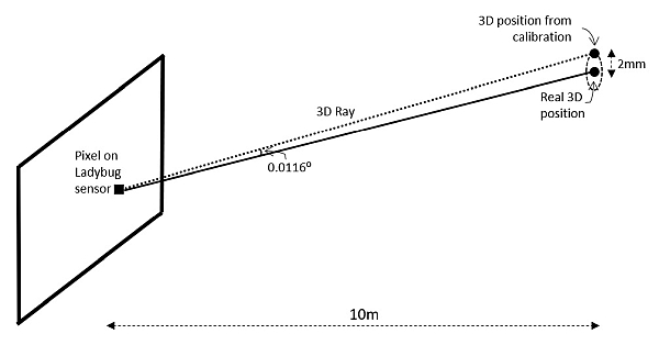
The average accuracy of a Ladybug camera is 2 mm at 10 m distance, or 0.0116 degrees, as illustrated below.
Local to Ladybug Transform Error
There is an error associated with how well the mathematical model can match the actual position and orientation of the lens with regards to the Ladybug camera coordinate system. This relates to the difference between the real physical position and the position calculated during camera calibration.
This is related to:
Relating Lens Coordinate Systems and the Ladybug Coordinate System
Converting a 3D Point to a Pixel Location
Rectification Error
There is an error associated with how well the mathematical model can match the underlying lens distortion.
This is related to:
Converting a Pixel Location to a 3D Ray
Converting a 3D Point to a Pixel Location
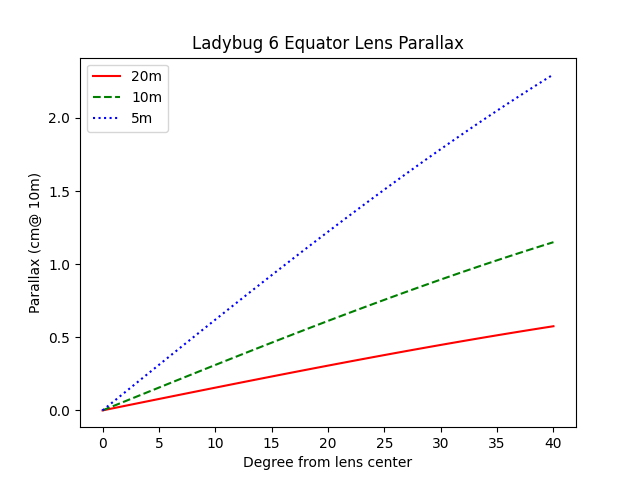
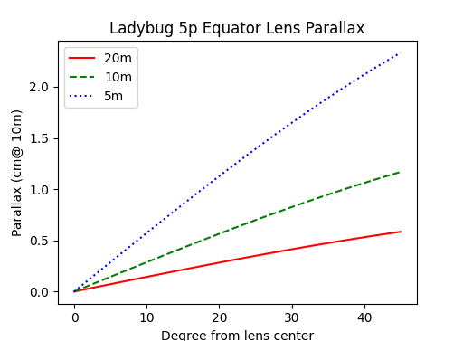
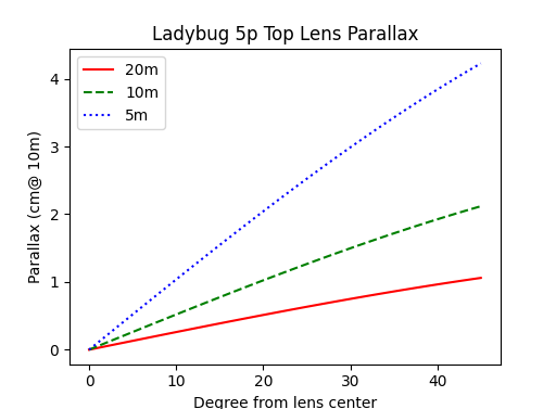
Parallax to Center of Camera Error
The parallax error is an additional source of error, not included in the 2 mm at 10 m accuracy stated above.
The parallax error is the difference between two rays pointing at the same destination from two different starting positions. In this case, the difference in position is between the lens center and the camera coordinate center.
The following diagrams show the angular difference observing the same point in 3D space between when the lens center is located at the real position and when the lens center is at the center of the Ladybug coordinate system.