How to Apply Dewarping on the Lepton® 3.1R and Lepton UW
1 Introduction
The infrared (IR) Lepton 3.1R and Lepton UW utilize a 95° wide field of view (WFOV) and 160° WFOV lens, respectively. Barrel distortion is created by the WFOV lens, causing the image’s center to be magnified slightly more than the edges. That makes straight lines appear to curve around the edge of the image. Barrel distortion is undesirable for many imaging applications. This application note describes applying distortion correction (dewarping) on the Lepton 3.1R and Lepton UW outputs using OpenCV built-in functions.
2 Image Distortion
2.1 Overview
A WFOV lens allows the imager to capture more in a scene but will cause distortion, making objects appear deformed. Generally, two types of distortion can exist in a camera: radial and tangential. Radial distortion is when straight lines curve either inwards to or outwards from the center, while tangential distortion is when the lens is tilted with respect to the image plane and the image appears skewed. To fix lens distortion, calibrate the camera to compute the transform matrices, which correct the camera’s mapping into the image plane.
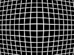
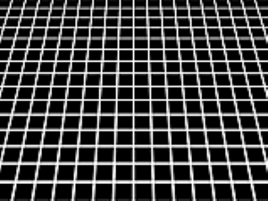
FIGURE 1. RADIAL DISTORTION (LEFT) AND TANGENTIAL DISTORTION (RIGHT)
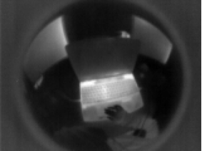
The calibration procedure slightly varies mathematically between Lepton 3.1R and Lepton UW. They have different lenses, so they do not image the same type of geometric distortion. Although both appear to have radial distortion, Lepton 3.1R images consist of linear borders, whereas Lepton UW has circular borders, commonly known as the fisheye effect. Mapping scene content into straight lines for the Lepton UW is more complex due to the extremely warped borders. Different distortion models corresponding to lens type are incorporated for calibration to compensate for this distinction: a wide-angle, rectilinear distortion model for Lepton 3.1R and a fisheye distortion model for Lepton UW.
2.2 Applying the Dewarp Transformation
To correct any lens distortion with OpenCV’s method, cameras are calibrated by capturing test patterns to model the distortion. Capturing calibration patterns using an IR camera is challenging, so using the default matrices characterizing the camera distortion below is recommended. A brief guide on how to take captures of the calibration pattern is described in Section 2.3.
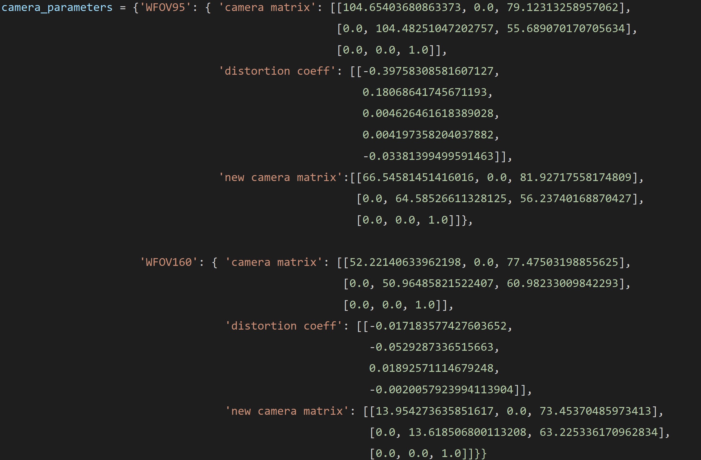
FIGURE 2. CAMERA MATRICES
These matrices, along with the input image, are passed in as arguments image into the following OpenCV built-in function to correct the camera-to-image plane mapping. A sample code in Python for demonstration is provided in Section 2.4.
Lepton 3.1R:
Lepton UW:

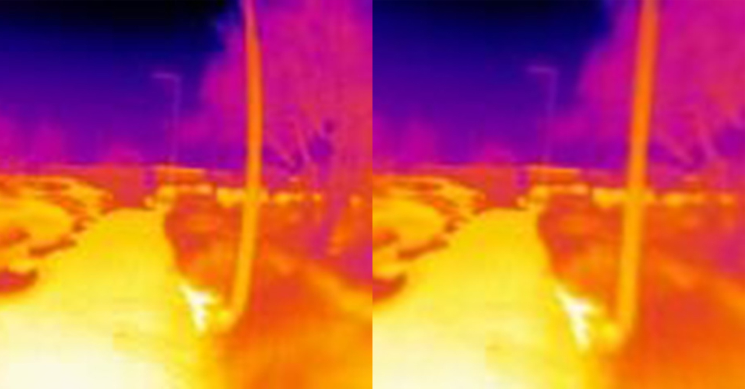
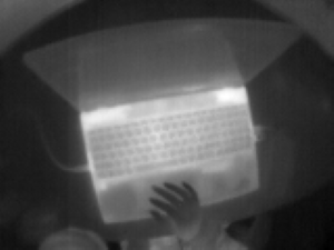
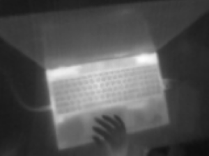
Notice that there is a camera matrix and a new camera matrix. Both represent intrinsic camera parameters; the only difference is that the camera matrix defines the original intrinsic camera parameters, whereas the new camera matrix scales and shifts the original camera matrix. Without specifying the new camera matrix in the undistort function, it uses the camera matrix by default, which outputs a rectilinear image with the same IFOV as its input. The tradeoff for obtaining straight lines is that some pixels in the corners of the input image are lost. Applying the new, all-pixel version camera matrix shown above provides the option to retain all pixels from the input, but it introduces black pixels around the borders. Figure 3 and 4 show the sample input and the possible outputs.
![]()
FIGURE 3. LEPTON 3.1R - ORIGINAL (LEFT), RECTILINEAR OUTPUT (CENTER), AND ALL PIXELS VERSION OUTPUT (RIGHT)
![]()
FIGURE 4. LEPTON UW - ORIGINAL (LEFT), RECTILINEAR OUTPUT (CENTER), AND ALL PIXELS VERSION OUTPUT (RIGHT)
2.3 Camera Calibration
Since the OpenCV website provides a thorough explanation and sample application code of the calibration process, this application note does not cover the details. The documentation can be found at https://docs.opencv.org/3.4/d4/d94/tutorial_camera_calibration.html.
As introduced in section 2.2, taking calibration pattern captures in IR is not straightforward. Please follow the guide below to take effective captures for IR camera calibration.
1. Setting Up
- Use a circle grid calibration pattern, as it is not ideal to display a thermal checkerboard. Asymmetrical or symmetrical circle grids work.
- An 8x8 circle grid is recommended.
- A paper printout of the calibration pattern glued on cardboard and briefly illuminated with high energy output lights, or the sun can create thermal contrast.
2. Taking the Captures
- Have at least a 6x6 circle grid for Lepton 3.1R and a 4x4 circle grid for Lepton UW visible in the capture.
- Some circles may be blurred near the image’s borders due to the WFOV.
- Each capture of the circle grid should occupy only portions of the FOV.
- The collection of captures should span most areas of the FOV, i.e., one or two captures of the circle grid near the center and eight to ten captures around the border of the FOV.
- Ten to twelve total captures will provide optimized calibration, and additional captures are not advantageous.
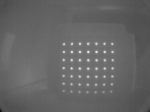
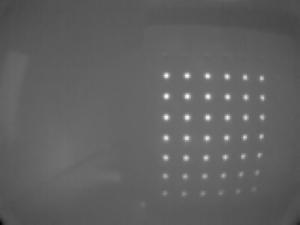
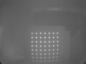
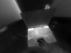
FIGURE 5. CENTER (LEFT), BOTTOM RIGHT (CENTER), AND BOTTOM CENTER (RIGHT) EXAMPLE LEPTON 3.1R CALIBRATION PATTERN CAPTURES
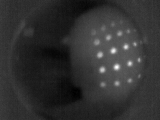
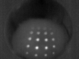
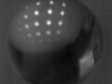
FIGURE 6. CENTER (LEFT), BOTTOM RIGHT (CENTER), AND BOTTOM CENTER (RIGHT) EXAMPLE LEPTON UW CALIBRATION PATTERN CAPTURES
2.4 Support
Sample script Lepton_Dewarp_example.py1 can be downloaded here.
For technical support, visit the FLIR Support Center at http://support.flir.com.
Related Articles
-
 Press Release
Teledyne FLIR Introduces Lepton 3.1R Radiometric Thermal Camera Module for Integrators
Read the story -
 Press Release
Teledyne FLIR’s New Online Support Tools for Boson+ and Hadron 640R Bring Faster Integration for Developers
Read the story -
 Press Release
Teledyne’s Thermal by FLIR program sees expansion with US Drone Makers BRINC and Teal
Read the story