Wiring configuration for Firefly® MV miniature IEEE-1394 connector
Download PDF - Wiring-FFMV-Mini-1394-Connector
Part Numbers
The part number for the miniature 8-pin vertical IEEE-1394 connector that is connected to the Firefly MV printed circuit board is BM08B-SRSS-TB(LF)(SN). It is made by JST Sales America. The female JST counterpart for this connector, which users must source and purchase themselves, is part number SHR-08V-S-B. This can be purchased through Digikey using Digikey part number is 455-1383-ND. Users will also require JST crimping part number SSH-003T-PO.2 in order to wire into the female connector as shown in Figure 1 above. This can also be purchased through Digikey using Digikey part number 455-1561-1-ND.
Pin Configurations
Miniature Vertical IEEE-1394 Connector
The pin configuration for the miniature vertical 8-pin IEEE-1394 JST connector, starting from the top (Pin 1) of the connector shown in Figure 1, is as follows:
|
Pin |
Function |
|
1 |
Shield |
|
2 |
Power Input (+8 to +32 VDC) |
|
3 |
DC GND |
|
4 |
TPB- |
|
5 |
TPB+ |
|
6 |
TPA- |
|
7 |
TPA+ |
|
8 |
Shield |
Standard IEEE-1394 Connector
For user reference, the pin configuration for the standard 6-pin IEEE-1394 connector is shown below, as it appears on a cable:
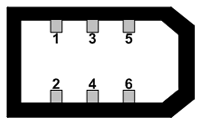
Figure 2: IEEE-1394 connector pin configuration (as it appears on cable)
|
Pin |
Function |
|
1 |
Power Input (+8 to +32 VDC) |
|
2 |
DC GND |
|
3 |
TPB- |
|
4 |
TPB+ |
|
5 |
TPA- |
|
6 |
TPA+ |
The signal on the Twisted Pair A is 1.0V DC. This voltage is then detected on the Twisted Pair B signal line; levels of 0.6 to 1.0V DC are used to determine when a device has been removed or added i.e. device attached >= 1.0V, device not attached <= 0.6V
Mapping the Connection from Camera to Host
In a standard 1394 cable, the Twisted Pair A and Twisted Pair B connections transpose from camera to host in the following manner:
TPA- → TPB-
TPA+ → TPB+
TPB z- → TPA-
TPB+ → TPA+
The following table shows how the connections should map from one end of a custom cable to another end. The left column shows the pins on the cable that connect to the 8-pin JST connector on the camera. The right column shows the pins on the cable that connect to a standard IEEE-1394 6-pin interface card connector.
|
able configuration for JST connector on camera |
Cable configuration for |
|
Pin 1 |
Shield |
|
Pin 2 |
Pin 1 |
|
Pin 3 |
Pin 2 |
|
Pin 4 |
Pin 5 |
|
Pin 5 |
Pin 6 |
|
Pin 6 |
Pin 3 |
|
Pin 7 |
Pin 4 |
|
Pin 8 |
Shield |
Related Articles
-
 Others
FLIR.de
Read the Story -
Others
FLIRArabia.com
Read the Story -
Others
FLIR.se
Read the Story