Transitioning from the Grasshopper to the Grasshopper2
Download PDF - Transition_GRAS_to_GS2_GigE
Frequently Asked Questions About Upgrading from the Grasshopper to the Grasshopper2
Is the Grasshopper being discontinued?
No, there are no plans to discontinue Grasshopper FireWire (GRAS-xx) models at this time. The new GigE Vision GS2-GE models are intended to give customers an alternative to the GRAS-xx to address issues such as cable length, as well as provide next-generation functionality such as opto-isolated general purpose I/O.
What other new hardware do I need to use the Grasshopper GS2-GE?
- Cable—Category 5, 5e or 6 cables up to 100 meters in length can be used (a significant improvement in distance over the FireWire standard). A 5-meter Category 5e cable can be purchased directly from Point Grey (Part No. ACC-01-2100)
- Interface Card—The camera will require a Gigabit Ethernet network interface card (NIC) with support for “jumbo packets” to run at full 1 Gbit/s transfer rates. We strongly recommend customers use PCI Express NICs with Intel Pro 1000 chipsets. This card can be purchased directly from Point Grey (Part No. ACC-01-1100). GigE network interface cards are also widely available at consumer electronics stores, or supported on board existing hardware.
- Power Supply—Power must be provided through the HR25 8-pin GPIO interface. The required input voltage is 12-24 V DC. A compatible 12 V wall-mount power supply and wiring harness can be purchased directly from Point Grey (Part No. ACC-01-9006).
A tripod adapter is included with the Grasshopper2 at no extra charge.
Can I run the Grasshopper2 GS2-GE with my existing FlyCapture-based application?
FlyCapture version 2.1 or later is required to control the GS2-GE and acquire images. Earlier versions do not support the GigE Vision-specific functionality that the camera implements.
How easy will it be to migrate my FireWire-based application for Grasshopper to the Grasshopper2?
The Grasshopper is an IIDC-1394 (FireWire) camera, while the Grasshopper2 is a GigE Vision camera. However, the IIDC-based control and status registers in the camera firmware, which are accessed by Point Grey’s FlyCapture API, remain mostly the same between the Grasshopper and Grasshopper2. As a result, upgrading an application from the Grasshopper to the Grasshopper2 should be fairly straightforward. Among the factors to consider are differences between versions 1.31 and 1.32 of the IIDC-1394 standard, supported pixel formats and modes (Grasshopper2 supports Format_7 only), and network management requirements for GigE Vision cameras. These differences, and others, are outlined in the following sections of this application note. Additionally, the FlyCapture SDK includes a GigEGrabEx sample program to show developers the basics of getting started in grabbing images with a GigE camera.
Can I use a GenICam-compliant application with the Grasshopper2?
Yes. The camera is loaded with a GenICam-compliant XML device description file. For a list of supported features or to access the file, consult the Grasshopper2 Technical Reference.
How does performance of the GigE network compare to that of the FireWire bus?
Data throughput on the IIDC-1394b bus is 800 Mb/s, while on the GigE network it is 1000 Mb/s. In practice, there is little measurable difference in performance, as approximately 15% of the GigE bandwidth is reserved for communications control data. Performance differences may be more noticeable in terms of load on the host CPU. GigE Vision applications may consume more resources because the CPU must process both data packet handling and image processing tasks. The CPU in FireWire systems handles only image processing tasks because data packets are delivered directly to main memory using direct memory access (DMA). To reduce GigE packet load on the CPU, Point Grey provides an Image Filter Driver, which is installed and enabled by default as part of downloading and installing the FlyCapture SDK. This driver works by isolating GigE Vision Streaming Protocol (GVSP) packets, and is recommended for improved image streaming performance on Windows systems. (On Linux systems, GigE Vision cameras communicate directly with native Ubuntu drivers.)
How does bandwidth management differ between GigE and FireWire in multiple-camera configurations?
The FireWire bus provides dedicated bandwidth and guaranteed timing for data packets, which guarantees packet delivery, particularly on systems with multiple cameras on the bus. In contrast, the User Datagram Protocol (UDP) used by the GigE Vision standard provides no guaranteed transmission or fixed timing mechanism. Bandwidth must be managed by adjusting packet size and packet delay, based on desired resolution and frame rate. These parameters are configurable using Point Grey’s FlyCapture API or the FlyCap demo program. Additional information about GigE bandwidth management is available in the Grasshopper2 Technical Reference.
How do I enumerate the Grasshopper2 camera on the GigE network?
Point Grey’s FlyCapture SDK includes an easy-to-use graphical interface tool for configuring the IP address of the camera and interface card. The Point Grey GigE Configurator provides IP configuration options based on the DHCP protocol, a persistent IP, or a link-local address (LLA). The IP address can also be configured programmatically using the FlyCapture SDK.
Does the Grasshopper2 GS2-GE support automatic inter-camera synchronization?
Not at this time. However, like all Point Grey cameras, the Grasshopper2 provides a GPIO connector and trigger functionality, which allows the start of exposure to be synchronized between multiple cameras using an external electrical signal.
General Considerations
Other Reference Documentation
Other useful sources of information regarding specific features of the Applicable Product(s) include:
- Grasshopper Getting Started Manual
- Grasshopper2 Getting Started Manual
- Grasshopper and Grasshopper2 Technical Reference Manuals
Testing Tools
To configure and test the information presented in this TAN:
- Connect the camera’s GPIO pins to an oscilloscope or external trigger source. By connecting the appropriate GPIO pins to an external trigger source or oscilloscope, you can observe the differences in general purpose input/output capability of the Applicable Product(s). Consult your camera’s Technical Reference or Getting Started manual for:
- GPIO connector pin layouts; and
- GPIO electrical characteristics
- Download the FlyCapture SDK. The SDK includes numerous example programs that demonstrate various camera features. Specific examples that relate to this TAN include CustomImageEx, AsyncTriggerEx and GigEGrabEx.
- Access the camera’s register space. The easiest way to try this is using the FlyCap demo software included with the FlyCapture SDK. For register definitions and individual bit descriptions, please refer to the Point Grey Digital Camera Register Reference or your camera’s Technical Reference manual.
Detailed Comparison Between Grasshopper and Grasshopper2
Mechanics
The Grasshopper and Grasshopper2 share many of the same form factor and general mechanical properties.
|
Description |
Grasshopper |
Grasshopper2 |
|
Data transfer and camera control connectors |
Two standard 9-pin IEEE-1394b connectors for data transfer, camera control and powering the camera |
One RJ-45 Ethernet jack for data transfer and camera control (power must be provided via the GPIO) |
|
Frame grabber requirements |
IEEE-1394b PCI, PCIe or ExpressCard |
Gigabit Ethernet network interface |
|
GPIO connector |
Hirose HR25 8 pin connector |
|
|
IR cut filter properties |
The infrared cut-off filter used with color versions of the cameras is the same and has the same transmittance properties. |
|
|
CCD sensor placement on PCB |
The chip and lens holder mounting holes are centered relative to the four corner mounting holes. |
|
|
Overall dimensions |
Industry standard 44mm x 29mm x 58mm (excluding lens holder, 1394/GigE and GPIO connector) |
|
|
Lens holder |
C-mount |
|
|
Case description |
Black zinc (casted) with black aluminum top and Point Grey logo |
|
|
Mass |
Approximately 85 g, depending on sensor (excluding optics) |
|
|
Tripod mounting bracket |
Secured by four (4) M2x2mm screws |
|
|
Mounting holes |
Three (3) M3x2.5mm holes on the bottom face |
|
|
Removable glass / IR filter system |
BW models: protective dust glass between sensor and optics |
|
|
Development kit |
Includes cable, 1394 interface card, software CD and Getting Started Manual. |
Not available. |
GPIO Properties
|
Pin |
Grasshopper |
Grasshopper2 |
|
GPIO0 (Pin 1) |
Bi-directional input/output |
Opto-isolated input |
|
GPIO1 (Pin 2) |
Bi-directional input/output |
Opto-isolated open collector output |
|
GPIO2 (Pin 3) |
Bi-directional input/output |
Bi-directional input/output |
|
GPIO3 (Pin 4) |
Bi-directional input/output |
Bi-directional input/output |
|
GND (Pin 5) |
Ground pin for all pins |
Ground pin for bi-directional IO, Vext, +3.3 V |
|
GND (Pin 6) |
Ground pin for all pins |
Ground pin for opto-isolated IO pins |
|
VEXT (Pin 7) |
Power camera externally |
|
|
+3.3V (Pin 8) |
Power external circuitry up to a total of 150 mA. |
|
Other Hardware and Electronics
|
Description |
Grasshopper |
Grasshopper2 |
|
CCD imaging sensors |
640x480 Kodak KAI-0340 |
1624x1224 Sony ICX274 |
|
Data transfer and camera control interface |
2X 9-pin IEEE-1394b (800Mb/s) |
1X RJ-45 Ethernet connector |
|
Power interfaces |
Via IEEE-1394b bus or GPIO connector |
Via GPIO connector only |
|
Power consumption |
Less than 4.0 W |
Less than 4.7 W |
|
Cable length/type supported |
10-meter FireWire |
100-meter Cat5, 5e, 6 |
|
A/D converter |
Analog Devices, 14-bit resolution |
|
|
Temperature Sensor |
On-board, accessible via control and status registers (CSRs) |
On-board; accessible via control and status registers (CSRs) |
|
Voltage Sensor |
||
|
Current Sensor |
None |
|
|
Case Temperature/Heat Dissipation |
Camera runs warm in high data rate video modes. Heat dissipation is encouraged but not required in normal operating environments. |
Camera runs at a higher temperature than Grasshopper and may require heat dissipation and active monitoring of ambient temperature. |
|
LED Behavior |
One general purpose status LED for monitoring camera power, initialization and FireWire activity. |
One general purpose status LED for monitoring camera power, initialization and video streaming activity. |
|
Automatic inter-camera image synchronization |
Cameras operating on the same FireWire bus are automatically synchronized. |
Not supported; requires external trigger |
Firmware
This section does not address the significant number of firmware enhancements that have been added in the Grasshopper2, but focuses on functional differences between the two cameras that could affect integration of the Grasshopper2 in existing Grasshopper-based applications. Users are encouraged to download the documents listed in Section 1.5.1: Other Reference Documentation for assistance with terms, camera specifications, and register definitions.
|
|
Many default startup (power-up) parameters, such as resolution, frame rate, and ROI have changed in the Grasshopper2. The memory channels on the Grasshopper2 can be used for creating new default settings. |

|
|
Point Grey cannot predict if or how all of the following differences may affect user applications. This section provides recommendations on how to address some of the most obvious differences in functionality. |
Format_7
|
Description |
Grasshopper |
Grasshopper2 |
|
Pixel Formats |
Mono8, Mono16, Raw8, Raw16, YUV411, YUV422, YUV444, RGB8 |
Mono8, Mono12, Mono16, Raw8, Raw12, Raw16, YUV411, YUV422, YUV444, RGB8 |
|
Max frame rates at max resolution |
|
|
|
1624x1224 Sony ICX274 |
30 FPS |
29 FPS |
|
2448x2048 Sony ICX625 |
15 FPS |
15 FPS |
|
Packet Size |
User-configurable |
By default, Format_7 packet size auto-adjusts to GigE Vision Stream Channel Packet Size setting, Stream Channel Packet Delay setting, and GigE link speed. |
|
Modes |
||
|
Mode_0 |
Region of interest only |
|
|
Mode_1 |
2X vertical binning and 2X horizontal subsampling; values are aggregated and averaged; limited or no increase in intensity |
2X vertical binning and 2X horizontal subsampling (monochrome models) or 2X vertical and 2x horizontal subsampling (color models); values are aggregated without averaging; increased intensity, improved SNR. |
|
Mode_2 |
2X vertical binning; values are aggregated and averaged, with limited or no increase in intensity |
Not available |
|
Mode_3 |
Region of interest only |
Not available |
|
Mode_4 |
Not available |
2X vertical binning and 2X horizontal subsampling; increased frame rate; available on color models only |
|
Mode_5 |
Not available |
4X vertical binning and 4X horizontal subsampling (monochrome models) or 4X vertical and 4x horizontal subsampling (color models); values are aggregated without averaging; increased intensity, improved SNR. |
|
Mode_6 |
Not available |
4X vertical binning and 4X horizontal subsampling; values are aggregated without averaging; increased intensity; available on color models only, in monochrome pixel formats only. |
|
Mode_7 |
Not available |
Region of interest only. Slower pixel clock, recommended for longer extended shutter times and/or improved imaging performance. Frame rate increase may not be possible with reduced ROI. |
|
Mode_8 |
Not available |
Region of interest only, maximum resolution 1600x1200 at 30 FPS. Available only on GS2-GE-20S4. |
Control and Status Registers (CSRs)
|
Description |
Grasshopper |
Grasshopper2 |
|
Redefined Registers |
||
|
LUT |
1A40h – 1A44h |
80000h – 80048h |
|
XMIT_FAILURE 12FCh |
No presence bit |
Presence bit |
|
FRAME_INFO 12F8h |
No inquiry bits for each embedded information type |
Inquiry bits for each information type |
|
New Registers |
||
|
Y16 Endianness |
Controlled using IMAGE_DATA_FORMAT 1048h |
DATA_DEPTH 630h |
|
Mirror Image |
MIRROR_IMAGE_CTRL 1054h |
|
|
Y8 or Y16 Grayscale or Raw Bayer Output |
BAYER_MONO_CTRL 1050h |
|
|
Current Sensor Access |
None |
CURRENT 1A58h – 1A5Ch |
|
GigE Vision Bootstrap Registers |
Not applicable |
Stream channel packet size, stream channel packet delay, heartbeat, and others. |
Other Firmware Changes
|
Description |
Grasshopper |
Grasshopper2 |
|
IIDC Version |
1.31 |
1.32 |
|
Pixel Format Standards |
Standard (Format_0 or Format_1) and customizable (Format_7) |
Customizable (Format_7) only |
|
Color processing |
Color models output greyscale information when run in standard (Format_0 or Format_1) Y8/Y16 modes. The conversion from raw Bayer information to greyscale is done on-board the camera. |
On color models, conversion from raw Bayer information to greyscale is done on-board the camera. |
|
Extended Shutter/Exposure Times |
Supported |
Up to 20 s in Format_7 Mode_7 only. Not available in other modes. |
|
High Dynamic Range (HDR) Imaging |
Not supported |
Support through HDR registers 1800h – 1884h |
|
Lookup table |
11-bit to 9-bit mapping |
9-bit to 9-bit mapping |
|
Trigger Modes |
IIDC modes 0, 1, 3, 14, 15: Supported on all models |
Supports multiple exposure modes. |
|
Memory Channels |
Two (2) channels for user-defined configuration sets; one (1) channel for restoring to factory default settings |
|
|
Frame Buffer |
32 MB for temporary image storage and re-transmission |
|
|
Non-Volatile Flash Memory |
512 KB for data storage |
|
|
Pixel Clocks |
Two (2) or more settings; may change with format/mode change |
One clock setting; will not change with format/mode change |
Software and Driver Support
|
Description |
Grasshopper |
Grasshopper2 |
|
Driver options |
Point Grey FirePRO driver |
Point Grey Image Filter driver (recommended on Windows) or Microsoft/Linux native drivers |
|
Bandwidth Management |
Guaranteed bandwidth for all cameras on bus |
Packet size and packet delay user configurable |
|
Camera Enumeration |
Enumeration on the FireWire bus is supported natively by the OS |
Point Grey GigE Configurator tool for camera enumeration; configuring MTU/IP address for camera and NIC |
|
FlyCapture 2.x Applications |
Supported |
Supported on v2.1 or later |
|
FlyCapture 1.x Applications |
Supported |
Not supported |
|
GenICam Applications |
Not supported |
Supported via on-board device description file. For a list of all supported features, see the Grasshopper2 Technical Reference. |
|
Supported Operating Systems |
Windows 2000 (PGRCAM driver only) |
Windows XP 32/64-bit |
|
Software Requirements with FlyCapture 2.1 |
MS Visual Studio 6.0 SP5 (to compile and run example code on Windows XP 32-bit) |
|
Related Articles
-
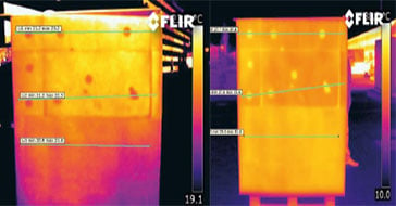 Application Story
FLIR cameras support analysis and diagnosis of external thermal insulation systems
Read the Story -
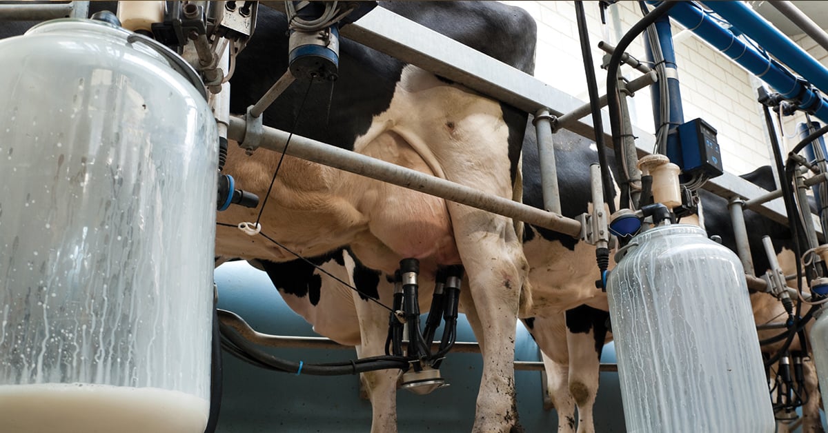 Case Study
Automatic Health Check in Dairy Farms Using FLIR Thermal Imaging Cameras
Read the Story -
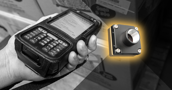 Deep Learning
Comparing Deep Learning Cameras with Smart Cameras
Read the Story