Buffering a GPIO pin strobe output signal using an optocoupler to drive external devices
Download PDF - Buffering_output_signal_to_drive_external_device
General Considerations
General Purpose Input/Output Pins
The Applicable Product(s) is/are equipped with a set of general purpose input/output (GPIO) pins that can be accessed via the GPIO connector on the back of the camera. Different products may use different connectors; consult your camera’s Technical Reference or Getting Started manual for part numbers and specifications, GPIO connector pin layouts, and GPIO electrical characteristics.
Testing Tools
To configure and test the information presented in this TAN:
- Connect the camera’s GPIO pins to an oscilloscope or external device. External devices can include an external light source or LED or other device that can be triggered. By connecting the appropriate GPIO pins to an external device or oscilloscope, you can verify that the camera is outputting a strobe pulse of the correct delay, duration and pattern. Consult your camera’s Technical Reference or Getting Started manual for:
- GPIO connector pin layouts; and
- GPIO electrical characteristics.
- Access the camera’s register space. The easiest way to try this is using the FlyCap demo software included with the PGR FlyCapture SDK. For register definitions and individual bit descriptions, please refer to the “Strobe Signal Output Registers” section of the PGR IEEE-1394 Digital Camera Register Reference.
Buffering GPIO Output
Buying an Off-the-Shelf Solution
An optocoupler with a buffered input, such as a Fairchild H11L1M, may work for a variety of situations. This part can be found at:
http://www.fairchildsemi.com/pf/H1/H11L1M.html
See the figure below for an example test circuit, showing a PGR Flea connected to the Fairchild H11L1-M, which is connected in turn to an LED.
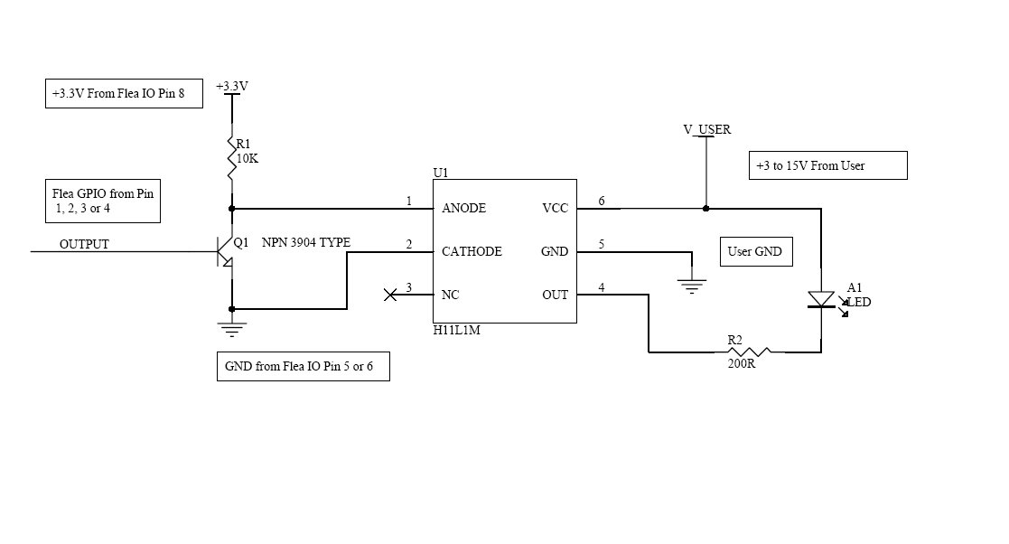
Figure 1: Fairchild H11L1-M Test Circuit for PGR Flea Camera
Building a Circuit (Advanced Users)
For users with electronics or electrical engineering knowledge who wish to build their own circuit to attach to (for example) an LED:
- Obtain a general purpose NPN transistor (for example, a 3904 type).
- Connect the base to the GPIO line, the emitter to ground, and the collector
to the cathode of the LED in the optoisolator. - The anode of the LED should be connected to +3.3V in series with an appropriate current limiting resistor (100 ohms for 33mA, 200 ohms for 16.5mA).
See the figure below for an example circuit diagram. In the case of the X-Strobe™ device described above, the NPN can be attached directly, since the optoisolator and resistor is internal to the strobe light.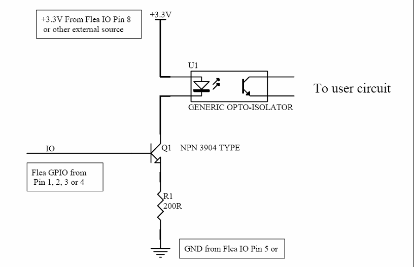
Figure 2: Example optocoupler interface for PGR Flea camera