Temperature Guns Versus Thermal Imaging Technology
- A spot pyrometer just gives you a number - thermal imaging cameras generate an image.
- A spot pyrometer reads the temperature of one single spot - a thermal imaging camera gives you temperature readings for each pixel of the entire thermal image.
- Because of advanced optics, thermal imaging cameras can also resolve temperatures from a longer distance. This allows you to quickly inspect large areas.
The spot pyrometer is also known as temperature gun or infrared thermometer. Because it works according to the same physical principle as a thermal camera, a spot pyrometer can be seen as a thermal camera with only one pixel. Such a tool can be very useful for many tasks, but because it only measures the temperature of one single spot the operator can easily miss crucial information. The high temperature of certain critical components that are near failure and need repair might go unnoticed.
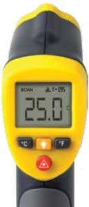
A temperature gun measures the temperature of one spot.
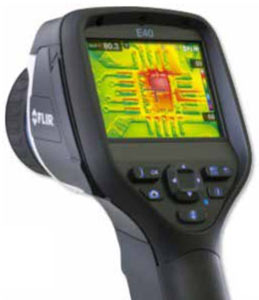
The FLIR E40sc thermal imaging camera measures the temperature of 19,200 spots.
Use Thousands of Spot Pyrometers at the Same Time
A thermal imaging camera also provides non-contact temperature readings, just like a spot pyrometer does. Unlike a spot pyrometer thermal imaging cameras produce not one, but thousands of temperature readings at the same time, one for each pixel in the thermal image. Using one thermal imaging camera therefore corresponds to thousands of spot pyrometer measurements. The FLIR E40sc thermal imaging camera has an image resolution of 160 x 120 pixels, resulting in 19,200 temperature readings at a glance. The FLIR T1030sc, one of the top models for industrial R&D/Science applications, has an image resolution of 1024 x 768 pixels, giving you 786,432 temperature readings at once.
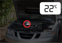
What a spot pyrometer 'sees'.
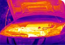
What a thermal imaging camera 'sees'.
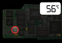
What a spot pyrometer 'sees'.
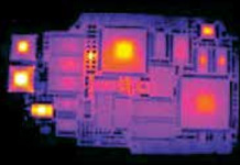
What a thermal imaging camera 'sees'.
Save Time and 'See' the Heat
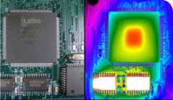
A thermal imaging camera not only gives you thousands of temperature readings, it also translates these readings into a thermal image. This conversion into an image results in a complete overview over the inspected equipment and allows the operator to immediately see small hot spots that would be easily missed with a spot pyrometer. Using a thermal imaging camera also saves time. Scanning large areas with many components using a spot pyrometer is a very time consuming task, because you have to scan every component separately. A thermal imaging camera can be used to check heat dissipation on printed circuit boards, to do quality checks or inspect thermal impact in the automotive sector, or to do failure analysis in the lab.
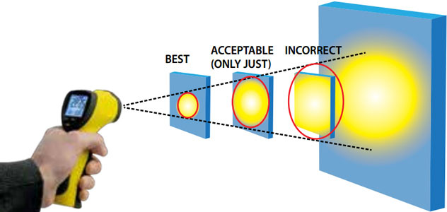
In order to accurately measure an object's temperature with a spot pyrometer the target object needs to entirely cover the measurement spot. This limits the distance from which temperatures can be measured accurately.
Another advantage of thermal imaging cameras compared to temperature guns is that they can accurately measure temperatures from larger distances. The distance at which a certain spot pyrometer is able to measure a target of a given size is often described with the “Distance to spot size ratio” (D:S) or ‘Spot Size Ratio’ (SSR). But where does that value come from and what does it stand for? The ‘spot size’ of a spot pyrometer is the smallest area that still can be measured accurately with the device. That means that the object of which you want to measure the temperature, also referred to as the target, needs to cover the entire spot size. The infrared radiation that is emitted by the target passes through the spot pyrometer’s optics and is projected onto the detector. If the object is smaller than the spot size, the detector will also be hit by parts of the radiation coming from the object’s surroundings. Hence, the device will not read the object’s temperature only but a mixture of the temperatures of the object and its surroundings.
The farther away you hold the spot pyrometer from the object that you want to measure, the larger the spot size will become, due to the nature of optics. Consequently, the smaller the target, the closer you need to hold the spot pyrometer in order to accurately measure its temperature. It is therefore very important to keep an eye on the spot size and make sure that you stand close enough to cover the entire spot size with the target, preferably even a bit closer to create a safety margin. The Spot Size Ratio defines a spot pyrometer’s spot size for any given distance to the target.
If the SSR of a spot pyrometer is 1:30, for instance, this means that the temperature of a spot with a size of 1 cm in diameter can be accurately measured at a distance of 30 cm. The temperature of a spot having a size of 4 cm can be measured from a distance of 120 cm (1.2 meters). Most spot pyrometers have an SSR between 1:5 and 1:50. This means that most spot pyrometers can measure the temperature of a target of 1 centimeter in diameter from a distance of 5 - 50 cm. Thermal imaging cameras are very similar to spot pyrometers in that infrared radiation is projected onto a detector matrix, with each single pixel in the image corresponding to a temperature measurement.
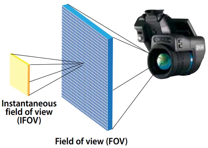
Thermal imaging camera producers usually do not specify SSR values to describe the spatial resolution of their products; but use instead the Instantaneous Field of View (IFOV). The IFOV is defined as the field of view of a single detector element of the camera’s detector array.
Theoretically the IFOV directly determines the spot size ratio of a thermal imaging camera. As the infrared radiation that is emitted by the target passes through the optics and is projected on the detector, the projected infrared radiation should completely cover at least one detector element, which corresponds to one pixel in the thermal image. So in theory covering one pixel in the thermal image should be sufficient to ensure correct temperature measurements. The IFOV is usually expressed in milliradians (one thousandth of a radian).
Thermal imaging cameras allow you to 'see' the heat.
The term radian describes the ratio between the length of an arc and its radius. One radian is mathematically defined as the angle formed when the length of a circular arc equals the radius of the circle. Since the circumference equals 2 π times the radius, one radian equals 1/(2 π) of the circle, or approximately 57.296 angular degrees and one mrad 0.057 angular degrees. In the situation where a thermal imaging camera is used to measure the temperature of a certain target we assume that the distance to the target equals the radius of the circle and we also consider the target to be rather flat. Since the viewing angle of a single detector element is small, we can assume that the tangent of this angle is approximately equal to its value in radian. Therefore, the spot size calculates as IFOV (in mrad) divided by 1000 and multiplied by the distance to the target.
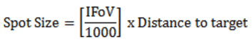
Where the IFOV is expressed in mrad.
Ideal and Real Optics
Using the formula you can calculate that a camera with an IFOV of 1.4 mrad will have a theoretical SSR of 1:714, so in theory you should be able to measure an object of 1 cm in diameter at a distance of more than 7 meters. However, as was stated previously this theoretical value does not correspond to real life situation, because it does not take into account the fact that real life optics are never completely perfect. The lens that projects the infrared radiation onto the detector can cause dispersion and other forms of optical aberration. You can never be sure that your target is exactly projected onto one single detector element. Projected infrared radiation can also ‘spill over’ from neighbor detector elements. In other words: the temperature of the surfaces surrounding the target might influence the temperature reading.
Just like with a spot pyrometer, where the target should not only cover the spot size entirely but should also cover a safety margin around the spot size, it is advisable to employ a safety margin when using a microbolometer thermal imaging camera for temperature measurements. This safety margin is captured in the term Measurement Field of View (MFOV). The MFOV describes the real measurement spot size of a thermal camera, in other words: the smallest measureable area for correct temperature readings. It is usually expressed as a multitude of the IFOV, the field of view of a single pixel.
A commonly used guideline for microbolometer cameras is that the target needs to cover an area at least 3 times the IFOV to take into account optical aberrations. This means that in the thermal image the target should not only cover one pixel, which in an ideal situation would have been sufficient for the measurement, but also the pixels around it. When this guideline is observed the formula to determine the spot size ratio can be adapted to take into account the factor of real optics. Instead of using 1xIFOV we can use the 3xIFOV guideline, which leads to the following, more realistic, formula:
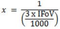
Where the IFOV is expressed in mrad.
Based on this formula a camera with an IFOV of 1.4 mrad will have an SSR of 1:238, which means that you should be able to measure an object of 1 cm in diameter at a distance of just under 2.4 meters. This theoretical value is likely on the conservative side, because of the safety margin observed. The real life SSR might therefore be higher, but using these conservative SSR values the accuracy of the temperature readings is safeguarded.
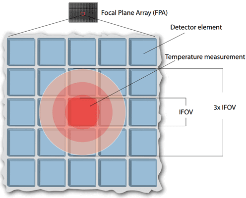
In the ideal situation the projected target should cover at least one pixel. To ensure accurate readings it is advisable to cover a wider area to account for the optical dispersion of the projection.
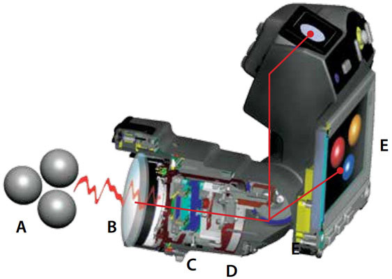
Infrared energy (A) coming from an object is focused by the optics (B) onto an infrared detector (C). The detector sends the information to sensor electronics (D) for image processing. The electronics translate the data coming from the detector into an image (E) that can be viewed in the viewfinder or on a standard video monitor or LCD screen.
Spot pyrometers have an SSR that usually falls between 1:5 and 1:50. Most of the affordable models have an SSR of 1:5 to 1:10, while the more advanced, and therefore more expensive, models reaching SSR values up to 1:40 or even 1:50. Note, however that spot pyrometers also have the same problem as thermal imaging cameras when it comes to optics. When comparing spot pyrometer specifications you must know if the SSR number refers to the theoretical value or to the one which is compensated for the imperfection of the optics.
Detect Temperatures from a Distance
Even when the factor of ideal versus realistic optics is taken into account the difference between thermal imaging cameras and spot pyrometers in measuring distance is huge. Most spot pyrometers cannot be held any farther away than 10 to 50 cm, assuming a 1 cm target. Most thermal imaging cameras can accurately measure the temperature of a target of this size (1 cm) from several meters away. Even the FLIR E40 thermal imaging camera, with an IFOV of 2.72 mrad, can measure the temperature of a spot of this size (1 cm) from more than 120 centimeters away. The FLIR T1030sc thermal imaging camera, one of FLIR’s most advanced models for industrial inspections, can measure temperature of a target of this size at a distance of more than seven meters with a standard 28° lens. These values are calculated assuming that the standard lens is used.
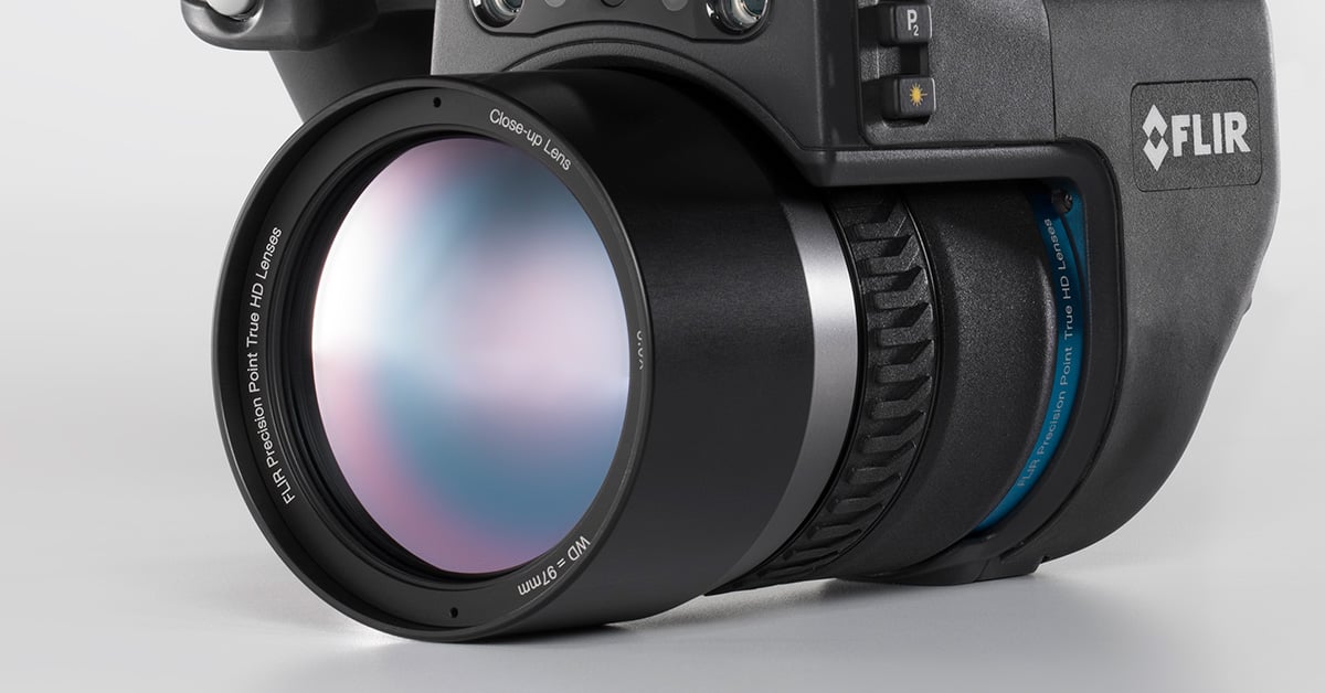
Many of the more advanced thermal imaging cameras feature interchangeable lenses. When a different lens is used this changes the IFOV, which in turn affects the spot size ratio. For the FLIR T1030sc thermal imaging camera, for instance, FLIR not only offers the standard 28° lens, but also a 12° telephoto lens. With this lens, which is developed especially for long distance observations, the spot size ratio is significantly larger. With the 12° telephoto lens the IFOV of a FLIR T1030sc thermal imaging camera is 0.20 milliradians. With this lens, the same thermal imaging camera can accurately measure the temperature of the same size target from a distance of almost 17 meters.
See Whether You Need to Move in Closer
Thermal imaging cameras clearly outperform spot pyrometers when it comes to the SSR values, but the SSR values only refer to the distance from which an accurate temperature measurement can be made. In real life detecting a hot spot does not always require an accurate temperature reading. The hot spot can be discernible in the thermal image even when the target covers only one pixel in the thermal image. The temperature reading might not be perfect, but the hot spot is detected and the operator can move closer to make sure that the target covers more pixels in the thermal image, ensuring that the temperature reading is correct.
Spot pyrometers also have challenges with measuring temperature on small objects. This capability is increasingly important for electronics inspection. As devices continue to get faster in processing speed, yet are required to fit into smaller packages, finding ways to dissipate the heat and identify hot spots is a real problem. A temperature gun can effectively detect and measure temperature, but its spot size is simply too large. However, thermal cameras with close-up optics can focus down to less than 5μm (micrometers) per pixel spot size. This allows engineers and technicians to make measurements on a very small scale.
Stop Guessing, Start Seeing
A spot pyrometer can only give you a number. That number might be inaccurate, which leaves you guessing. A thermal imaging camera allows you to ‘see’ the heat, giving you not only temperature measurements, but also an instant image of heat distribution. This combination of visual information and accurate temperature measurements enables you to find faults quickly and accurately. Stop guessing, upgrade to a thermal imaging camera from FLIR Systems and start finding problems faster and easier.
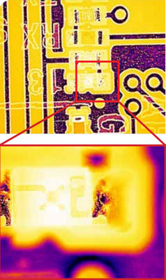
Close-up and microscopic lenses provide great image detail and allow you to measure small spots. This would be extremely difficult to do with a spot pyrometer. The top image was taken with a 4x close-up lens, the bottom image with a 15 micron lens.
Related Articles
-
 Fundamentals
What Are IR Camera Lenses Made Of?
Learn more -
 Tech Note
Can Thermal Imaging See Through Fog and Rain?
Read the Story -
 Tech Note
FLIR Machine Vision Cameras Capture High-Definition Footage of NASA’s Perseverance Rover Landing on Mars
Read the story