Best Filtering Practices For Accurate Fired Furnace Tube Measurement
Thermal imaging is an ideal non-contact inspection tool for tubes inside a working oil-refining furnace, but performing temperature measurement through flames is challenging. Fortunately, new filtering techniques are improving the accuracy of such measurements.
Inspecting the tubes inside a working oil-refining furnace is critical to maximizing safety, efficiency and lifetime. But performing infrared (IR) imaging and temperature measurement through the hot gases in a working furnace is challenging. The solution is an optical gas imaging camera fitted with a special filter that allows inspectors to take accurate measurements inside active furnaces.
In the petrochemical industry, processing crude oil into other products involves heating it to temperatures above 400°C using furnaces. This is typically done by pumping it through tubes inside furnaces, where burners heat the tubes and thus the oil inside them. It’s critical to have good control of surface temperature along the tubes. If parts of them are just 50°C too hot, tubes designed to last for 20 to 25 years could fail in five years. On the other hand, operating a furnace too cool can significantly reduce the efficiency of the system, resulting in less throughput.
DOWNLOAD THE APP NOTE
Seeing Into A Furnace
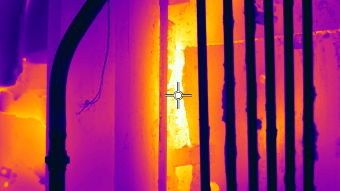
It’s therefore important to look past the hot gas and measure the temperature of the tubes. One way to measure is by using a thermocouple, a temperature sensor attached to the tube. Though they do provide useful information, thermocouples can only measure the temperature of the spot where they’re attached. You have to trust that the temperature is consistent around the thermocouple because it won’t detect heat spikes nearby (see Fig. 1).
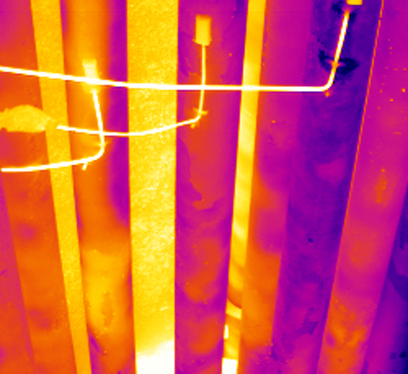
Fig. 1. Thermocouples on tubes fail to detect hotter areas nearby, which appear brighter in this image, only measuring their own local spot temperature.
A furnace camera such as the FLIR GF309 can view a larger area of tubes and measure the heat within the imaging area. If there are variations in temperature from one part of the tube to another, the camera can detect that.
The burners heating a furnace generate vapors and gases that most IR cameras can’t see through clearly. But special thermal imaging cameras with spectral filters are able to see through, measuring temperature variations on tubes behind them.
Inside And Out
What might cause such variations? Two processes can interfere with the smooth transfer of heat from the burner’s flames, through the tube, to the oil inside. One is called scaling, when excessive heat causes the formation of an oxide layer on the external surface of the tube. These oxide layers can vary in emissivity, be thin or thick, absorb heat and have poor conductivity, which limits the heat transfer into the tubes. These areas appear hotter in the IR image, although in reality they are keeping the process too cool by blocking the passage of some heat into the tube (see Fig. 2).
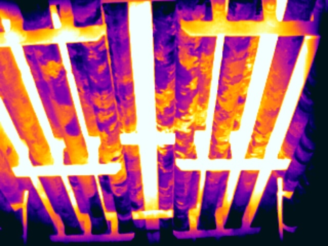
Fig. 2. External scaling on the tubes leads to a patchy appearance, both in infrared and visible light. Areas with defined edges that appear hot in the thermal image are actually not overheating.
While scaling causes apparent overheating, a different problem—coking—causes actual overheating. Coking is caused by a localized increase in temperature, which can decompose the crude oil into carbon and hydrogen. While the hydrogen follows the oil flow, the carbon can stick and build up in localized areas on the internal surface of the tubes. The buildup impedes the flow of oil, which normally carries away some of the heat from the tube as it flows, and causes that section of tube to become too hot.
Say you’re looking at a section of tube that is generally 400°C. There might be a small area with an increased temperature of 450°C somewhere on the tube fronting the burners; it’s usually the side fronting the burners because they’re subjected most directly to heat, so both scaling and coking more likely appear there. In a thermal image, that hotter area will clearly have a different color compared to the surrounding tube. But how do we know if such an overheating is scaling or coking?
Telling The Difference
Because coking and scaling are two different problems—one causing apparent overheating while the other leads to real overheating—it’s important to be able to tell them apart. Scaling is typically indicated by a sharp thermal gradient and often by a patchy appearance that can be seen in both visible light and in the IR image. If the visible pattern matches the IR pattern, the issue is likely scaling. Coking typically shows a smoother thermal gradient in the IR image—often referred to as a “ghostly glow”—that doesn’t correspond to any visible feature on the tube’s surface (see Fig. 3). Telling the difference and quantifying temperature variances requires a good-quality image. To acquire such an image, IR cameras use filters that can remove the heat of the vapors and gases from the picture, essentially seeing through the furnace to the tubes. Without proper filtering, the image can appear cloudy. The cloudiness can significantly degrade the accuracy of the temperature measurement and make it difficult to tell if overheated areas are the result of coking or scaling.
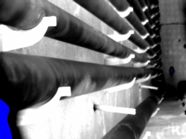
Fig. 3. Areas of the tubes suffering from internal coking show soft edges and a “ghostly glow” in the thermal image, indicating actual hotter tube areas that might be overheating.
A thermal-imaging camera might have an InSb detector with a filter that only passes radiation with a wavelength of 3.9 μm. At that wavelength, vapor and gases in the furnace emit little or no radiation, so they’re functionally invisible, and the majority of photons collected by the detector come from other objects behind the vapor. Both the detector and that filter are contained in the part of the camera that is cooled to below 70 Kelvin to reduce noise and self-heating of the filter that would negatively impact image and accuracy.
These cameras might also have a drop-in neutral density filter, outside the cooled area, which removes a certain percentage of radiation across a wide range of wavelengths to prevent oversaturation of the detector at high scene temperatures. This setup, however, can still have problems with an undesired phenomenon called stray light, excess radiation that finds its way to the detector.
Going Astray
Stray light is not much of a problem in many types of thermal measurements, especially not when the object being measured is warmer than the surrounding area. But in furnaces, the surrounding area is typically much hotter than the tubes themselves, and that can lead to problems. Stray light happens when IR photons reflect off various surfaces and travel along undesired paths. It can come from within the camera’s field of view, or from hot objects outside the field of view, such as a burner. The stray light can bounce around inside the camera until it reaches the detector, creating a cloudy effect that reduces the quality of the image and affects the accuracy of the temperature measurements (see Fig. 4).
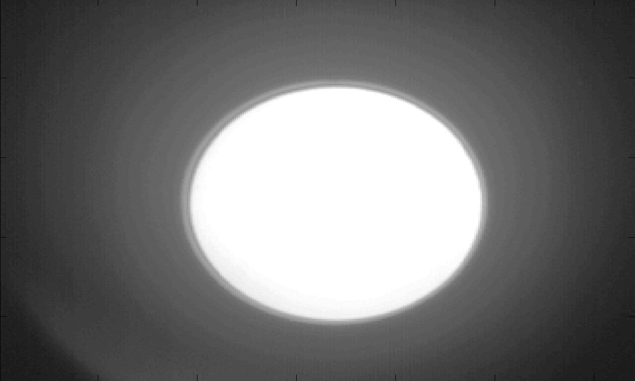
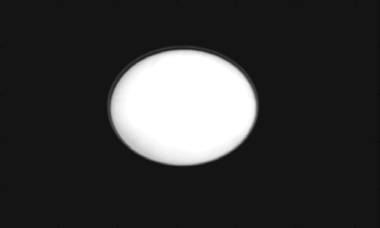
Fig. 4. A warm blackbody imaged with a neutral density filter (top) shows a cloudy appearance due to stray light. The same object viewed through an aperture (bottom) is much sharper. Note: The cloudiness in the top image has been magnified to more visually illustrate the difference.
A New Approach
To solve the stray light problem, neutral- density filters can be replaced with an aperture. The aperture is an aluminum plate with a small hole in it, and it blocks a large percentage of the radiation, just as a neutraldensity filter does. The plate is coated on both sides with IR black, a coating that absorbs IR radiation. Stray light that hits the outside of the aperture is absorbed so it cannot bounce further into the camera. An additional benefit of the aperture is that it increases the camera’s depth of field, so that more parts of the tubes can be in focus at the same time. That allows a thermographer to inspect a wider swath of tubes at once (see Fig. 5).
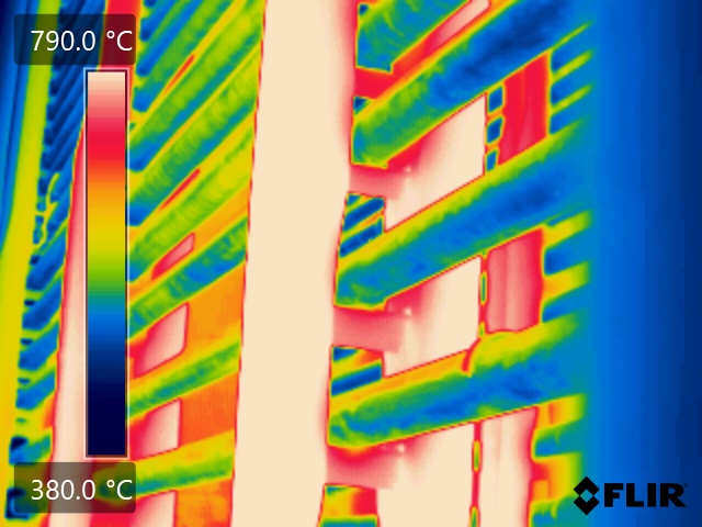
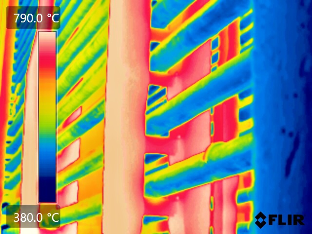
Fig. 5. These images were taken through the same viewport, one with an aperture (bottom) and one with a neutral density filter (top). The sidewall of the viewport, along the right side of each image, is more clearly in focus with the aperture. (Credit: Mikael Cronholm)
Of course, heat of several hundred degrees Celsius coming from a furnace would be enough to melt not only the IR black coating but also the camera itself. So the camera should always be operated with a front heat shield and an additional front protective window that suppresses unwanted wavelengths.
The Limits Of Measurement
In a recent test, a camera was pointed through the inspection port of a furnace at a blackbody radiator with a known temperature and emissivity on the other side of the furnace. The use of a coated aperture cut the measurement error in half, by efficiently suppressing stray light. Other factors also affect the accuracy of the measurement; it works best with clean-burning natural gas fueling the burners, because variations in the furnaces or impurities in the fuel can change the wavelengths emitted by the vapors, introducing errors.
Another limitation is imposed by the inspection port, essentially a peephole in the side of the furnace. The furnaces have walls perhaps half a meter thick to hold the heat in, and the ports tend to be small. Pointing the camera straight at the port provides only a straight-ahead view, limiting the area that can be imaged. Users can add a lens extender, a slim device that fits further into the peephole and can be panned around to see more of the tubes, thus increasing the chance of finding any problems.
A Useful Tool
Thermal imaging cameras are an important tool for gathering temperature measurements of the tubes inside furnaces used for oil refining and petrochemical processing, providing more detailed measurements than thermocouples. Though seeing through gases in a furnace can be challenging, it’s important it be done accurately, because tube temperatures just 50°C too high can significantly reduce the lifetime of the tubes.
Choosing the right filter setup can affect the accuracy of the measurement and help users distinguish between external scaling and internal coking. Using a neutral density filter alleviates the problem of over-saturation of the detector but does not eliminate stray light, which can bounce into the detector and create a cloudy, less useful image. A new technique relies instead on an aperture, a small hole in an aluminum plate coated with IR black to absorb stray light before it can reach the detector.
By choosing the right filter setup and taking into account other factors that can affect accuracy, such as the purity of the fuel gas and the efficiency of the burner, furnace inspectors can assess how well the process works and catch problems before they create added expense.
Related Articles
-
 Recorded Webinar
An Introduction to Thermography for Furnace Inspections
Watch now -
 Application Story
FLIR thermal imaging cameras reveal what’s behind the flames
Read the Story -
 Application Story
Through-Flame Thermal Cameras Can Take the Heat
Read the Story